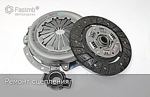
The article describes in detail the process of disassembling, repairing and reassembling the clutch on a VAZ car. The article describes in detail the process of disassembling, repairing and reassembling the clutch on a VAZ car.

The clutch plays one of the most important roles in the movement of the car and at the first manifestations of violations of its operation, it is necessary to immediately start repairing, otherwise inaction can lead to sad consequences, then the money for repairs will take much more time. Before removing this mechanism, the clutch diagram will come in handy, study it in detail for further repairs and the concept of the principle of operation.
We removed and repaired the clutch disc on a VAZ 2110 car, similar equipment is on 2111 and on later models of these cars, but on the VAZ 2112 car there are some differences and improvements, in particular, modifications were made: the springs of the damper of the driven disc and the leading part of the clutch, but the essence of the repair remains the same.
Dismantling and repair of a car clutch:
1. The first step is to dismantle the gearbox. The procedure requires patience, and without it, it will be impossible to repair the clutch.

2. Place a mandrel in the center passage of the disc. It can be made independently according to the dimensions of the existing shaft, or you can use the input shaft instead, which was borrowed from another car.
3. Replace one bolt holding the gearbox in place, and using a long screwdriver, hold the flywheel so that it does not turn when the other hand unscrews the six bolts holding the clutch cover.
Now you can remove the flywheel complete with the driven and pressure plate. When removing the clutch cover, hold the clutch disc inside it so that it does not fall out.

4. If some elements of the clutch disc have cracks or rough scratches, then it must be replaced with a new one. For this you need:
- 1 - check the friction linings for wear;
- 2 - check the rivet heads. They must be lowered into the depth of the friction linings by more than 0.3 mm;
- 3 - check the damper springs in the sockets of the disc hub for tightness, if they burst or loosened strongly, then the driven disc should be replaced with a new or old one, but serviceable.
5. If visually from the end of the driven disk it is visible that there is a distortion of its shape, then check the runout of the disk, and if it is more than half a millimeter, then this part must be completely changed.

6. Next, inspect the surface of the pressure plate and flywheel, if rough disc abrasion (wear), deep scratches or dents are noticed, then the flywheel or pressure plate must be replaced with a new one. Grinding won't help!
7. Next, turn the casing over to the other side and continue inspection:
- 1 - riveted joints of the pressure plate and the casing. They should not have weakening and obvious defects, if any, then you will have to change the disc in the kit.
- 2 - diaphragm springs of the pressure plate. They should also not be with obvious defects (deep scratches, cracks and chips), if defects are noticeable, then replace the entire casing.
- 3 - contacts of diaphragm spring petals. All limbs (contacts) of metal petals with clutch release bearings must be free from defects and in the same plane (a maximum wear difference of 0.8 mm is allowed). If the wear is more than 0.8 mm or there are serious defects, then again there is only one way out - to replace the disc in the kit.

8. Also, the pressure plate with the casing must be replaced as an assembly if the support rings of the pressure spring are cracked, chipped or otherwise physically altered.
9. If desired and possible in the garage, you can test the operation of the leading part of the clutch. To do this, it is necessary to fix the pressure plate (3) complete with the casing (2) and the pressure spring (1) on the equipment with an intermediate ring (4) whose thickness (B = 8.3 ± 0.03 mm). This equipment replaces the flywheel driven disc.
Now disengage the clutch three times with a disengagement stroke of 8–9 mm, applying a load to the pressure spring petals (1) on the diameter C = 34 mm. Wherein:
- size A must be within the range of 29–31 mm;
- check that the switch-off stroke of 8.0 ± 0.1 mm corresponds to a stroke of the pressure plate of at least 1.4 mm;
- the difference in the values of the withdrawal of the pressure disk (3) is not more than 0.25 mm;
- the load on the petals of the pressure spring (1) on diameter C at a stroke of 8.0 ± 0.1 mm should be no more than 1100 N (1350 N for the VAZ-2112 clutch), the peak off load no more than 1300 N (1500 N for the VAZ clutch –2112).
10. Before reassembling the clutch, it is necessary to check the freedom of movement of the driven disc along the splines of the input shaft of the gearbox. If there are seizures, eliminate them, if necessary, replace the damaged parts.

11. When reassembling the driven disc into the pressure casing, carefully make sure that the part of the protruding hub faces the pressure spring.
12. From the side of the compression spring, insert a centering mandrel into the splines of the driven disc.
13. In the photo, the arrows mark three centering pins, along them, just like me, you need to install the clutch on the flywheel, and then holding the flywheel with a screwdriver from scrolling, tighten the 6 bolts securing the clutch to the flywheel.
14. Now you can remove the centering mandrel from the clutch disc and reinstall the gearbox. Clutch repair completed.